The 555 is capable of sinking and sourcing up to 200mA, but it gets very hot when doing this on a 12v supply. The following circuit shows the maximum number of white LEDs that can be realistically driven from a 555 and we have limited the total current to about 130mA as each LED is designed to pass about 17mA to 22mA maximum. A white LED drops a characteristic 3.2v to 3.6v and this means only 3 LEDs can be placed in series. 
Monday, February 21, 2011
DRIVING MANY LEDS CIRCUIT
BI-POLAR LED DRIVER CIRCUIT
Some 2-leaded LEDs produce red and green. These are called Bi-polar LEDs. This circuit alternately flashes a red/green bi-polar LED:

Wednesday, February 16, 2011
LM3909 LED Flasher
The LM3909 is an integrated circuit (IC) which will flash a light-emitting diode (LED). Using only two extra components and a battery, the circuit is cheap and has a very low current drain from a 1.5 V cell. The circuit can be used as a novelty flasher, an indicator for a dummy alarm bell box, or it could be attached to a torch so that it could be found easily in the dark! The simple circuit is shown in Figure

LED FLASHER WITH ONE TRANSISTOR!

This is a novel flasher circuit using a single driver transistor that takes its flash-rate from

a flashing LED. The flasher in the photo is 3mm. An ordinary LED will not work. The flash rate cannot be altered by the brightness of the high-bright white LED can be adjusted by altering the 1k resistor across the 100u electrolytic to 4k7 or 10k. The 1k resistor discharges the 100u so that when the transistor turns on, the charging current into the 100u illuminates the white LED. If a 10k discharge resistor is used, the 100u is not fully discharged and the LED does not flash as bright. All the parts in the photo are in the same places as in the circuit diagram to make it easy to see how the parts are connected.
FLASHING TWO LEDS
These two circuits will flash two LEDs very bright and consume less than 2mA average current. They require 6v supply. The 330k may need to be 470k to produce flashing on 6v as 330k turns on the first transistor too much and the 10u does not turn the first transistor off a small amount when it becomes fully charged and thus cycling is not produced. 
3v WHITE LED FLASHER

This will flash a white LED, on 3v supply and produce a very bright flash. The circuit produces a voltage higher than 5v if the LED is not in circuit but the LED limits the voltage to its characteristic voltage of 3.2v to 3.6v. The circuit takes about 2mA an is actually a voltage-doubler (voltage incrementer) arrangement. Note the 10k in series with the LED charges the 100u. It does not illuminate the LED because the 100u is charging and the voltage across it is always less than 3v. When the two transistors conduct, the collector of the BC557 rises to rail voltage and pulls the 100u HIGH. The negative of the 100u effectively sits just below the positive rail and the positive of the electro is about 2v higher than this. All the energy in the electro is pumped into the LED to produce a very bright flash.
5-LED CHASER

The LEDs in this circuit produce a chasing pattern similar the running LEDs display in video shops. All transistors will try to come on at the same time when the power is applied, but some will be faster due to their internal characteristics and some will get a different turn-on current due to the exact value of the 22u electrolytics. The last 22u will delay the voltage-rise to the base of the first transistor and make the circuit start reliably.
The circuit can be extended to any number of odd stages.
AUTOMATIC GARDEN LIGHT

This circuit automatically turns on and illuminates the LEDs when the solar panel does not detect any light. It switches off when the solar panel produces more than 1v and charges the battery when the panel produces more than 1.5v + 0.6v = 2.1v
BUCK CONVERTER for HIGH-POWER LED 210mA

This circuit will drive 1 high-power white LED from a 12v supply and is capable of delivering 210mA. The driver transistor is BD 139 and the details of the inductor are shown above. The voltage across the LED is approx 3.3v - 3.5vThe driver transistor will need a small heatsink. The 2R2 can be increased if a lower drive-current is required.
BUCK CONVERTER for HIGH-POWER LED 48mA to 90mA

This circuit is a "Buck Converter" meaning the supply is greater than the voltage of the LED. It will drive 1 high-power white LED from a 12v supply and is capable of delivering 48mA when R = 5R6 or 90mA when R = 2R2.
The LED is much brighter when using this circuit, compared with a series resistor delivering the same current. But changing R from 5R6 to 2R2 does not double the brightness. It only increases it a small amount.
The inductor consists of 60 turns of 0.25mm wire, on a 15mm length of ferrite rod, 10mm diameter. Frequency of operation: approx 1MHz. The circuit is not designed to drive one 20mA LED.This circuit draws the maximum for a BC 338
LED TORCH with ADJUSTABLE BRIGHTNESS

This circuit will drive up to 3 high-bright white LEDs from a 3v supply. The circuit has a pot to adjust the brightness to provide optimum brightness for the current you wish to draw from the battery.
The transformer is wound on a ferrite slug 2.6mm dia and 6mm long as shown in the LED Torch with 1.5v Supply project.
This circuit is a "Boost Converter" meaning the supply is less than the voltage of the LEDs. If the supply is greater than the voltage across the LEDs, they will be damaged.
1v5 WHITE LED DRIVER

This circuit will drive a super-bright white LED from a 1.5v cell. The 60 turn inductor is wound on a small ferrite slug 2.6mm dia and 6mm long with 0.25mm wire.
The main difference between this circuit and the two circuits above is the use of a single winding and the feedback to produce oscillation comes from a 1n capacitor driving a high gain amplifier made up of two transistors.
The feedback is actually positive feedback via the 1n and this turns on the two transistors more and more until finally they are fully turned on and no more feedback signal is passed though the 1n. At this point they start to turn off and the signal through the 1n turns them off more and more until they are fully turned off. The 33k turns on the BC557 to start the cycle again.

If you do not have a ferrite slug, the inductor can be made from a machine screw 10mm long and about 3-4mm dia. Wind 150 turns of 0.25mm wire. Or you can use a brass ferrule 20mm long x 5mm. Wind 150 turns.
RESULTS for the same brightness:
Slug: 21mA
Brass Spacer: 18mA
Machine screw: 14mA
WHITE LED FLASHER

This circuit will flash a super-bright white LED from a 1.5v cell. The transformer is wound on a small ferrite slug 2.6mm dia and 6mm long as shown in a project above. The circuit uses the zener characteristic of the reverse-base-emitter junction of a BC 547 to pass current and flash the LED.
LED TORCH with 1.5v SUPPLY

This simple circuit will illuminate a super-bright white LED to full brightness with 28mA from a 1.5v cell. The LED is 20,000mcd (20cd @ 15° viewing angle) and has an output of approx 1lumen.
The transformer is wound on a small ferrite slug 2.6mm dia and 6mm long. It is made from F29 ferrite material as the circuit operates at a high frequency (100kHz to 500kHz).
The efficiency of the circuit revolves around the fact that a LED will produce a very high output when delivered pulses, but the overall current will be less than a steady DC current.
BC 337 has a collector-emitter voltage of 45v. (BC338 has 25v collector-emitter voltage rating.) The voltage across the transistor is no more than 4v as the LED absorbs the spikes. Do not remove the LED as the spikes from the transformer will damage the transistor. The circuit will drive 1 or 2 while LEDs in series.
Low-battery indicator with LED flasher

Typical low-battery indicators simply turn on an LED when the battery voltage drops below a certain value. Such circuits actually accelerate the battery’s extinction by drawing excessive current. This circuit draws a mere 1 mA in its standby mode and averages only 20 m A when activated. The low current imposes a minimal burden on any battery circuit.
Diac controlled LED flasher
This is probably the simplest idea to generate flashing light from an LED using AC. The circuit is relatively the simple way of flashing one or more LEDs from a high voltage DC obtained from Mains. This can be used as a Mains indicator or Mock flasher.
The circuit uses a diac for the alternate switching of LED. The diac is usually used in pulse generator circuits to trigger SCR and Triac. If a low voltage passes through a diac, it simply behaves like an open circuit and only very low current passes through it. But if the voltage increases to the breakdown threshold of the diac, it will pass heavy current. Usually 35 volt DC is required to attain the threshold level of diac. Unlike SCR, diac conduct in both the directions. In the circuit, a commonly available DB3 diac is used. Diode D1 rectifies AC and generates a high volt DC. Resistor R1 safely controls the DC to operate diac and LED.
Normally LED will be OFF. When the capacitor charges fully, diac gets the threshold voltage and fires. This provides current to LED and it lights. Resistor R2 makes the LED current to a safer value of 30 mA. When the diac conducts, C1 discharges and again the breakdown voltage of diac decreases and LED turns off. Thus the charging/discharging cycles of C1 makes the LED flashing. The value of C1 determines the flash rate. Higher values give slow flash rate and vice versa. If the threshold level of diac is not obtained using the given value of R1, reduce it to 10K, but its wattage should be increased to 5 watts.
Caution: The circuit is directly connected to high volt AC and there is no galvanic isolation. Take utmost care while handling the circuit. Enclose it in a shock proof case. Do not touch any points when it is connected to Mains.
Diac controlled Flasher Circuit

Read more: http://electroschematics.com/4488/diac-controlled-led-flasher-3/#ixzz1E7NHiqF9
4017 Led Pattern-Flasher
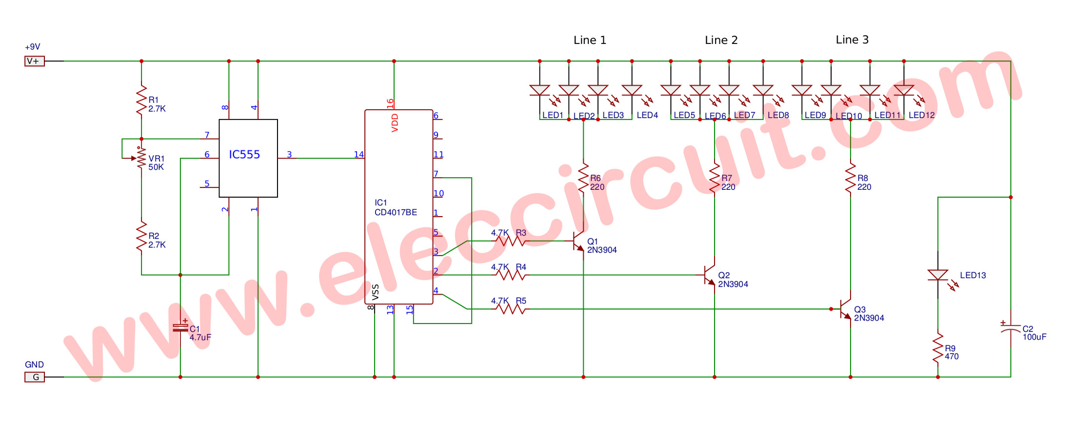
The circuit uses a 555 timer oscillator to supply clock pulses of a variable frequency to the 4017 decade counter. The decade counter only needs to have three outputs so the fourth output goes into the reset pin to start the cycle all over again. The central red led is always on. Each row of four leds flash in sequence giving the impression that the light is rotating. It is an idea that works very well giving an eye-catching display. It will run continuously for three hours with a standard pp3 battery.
Read More Source:http://www.geocities.com/electronics3456/4017.html
12 LED Flasher
LED flasher in this circuit use 12 LED it can show 2 style .The circuit consist 2 section
1.pule generate circuit
2.Counter-Display circuit
![]()
![]()

Figure 1. Schematics of 12 LED Flasher
THE FLIP FLOP
This is the simplest circuit capable of alternately flashing two LEDs. The flash-rate is determined by the two 10k resistors and two 100u electrolytics. The flash-rate can be increased or decreased and one LED can be made to flash brighter by altering the 4 components.
The operation of the circuit is fully discussed in the Basic Electronics Course P17 & P19 (subscription needed) and in 5 Projects P16. (use this link for the web: 5 Projects)
It can be purchased as one of the kits in 5 Projects. (use this link for the web: 5 Projects)
This circuit does not have the advantage of the two described above. It does not pulse the LED with a high current for a short period of time and thus it is not as efficient as the two above. When a LED is pulsed with a high current for a very short period of time, the output is almost as bright as a constant, lower-current.
THE FLIP FLOP
Here are some Flashing LED circuits from "200 Transistor Circuits' eBook. The first 4 circuits show how to change an NPN transistor for PNP.
1.5v LED FLASHER
The next circuit flashes a LED and uses a 1.5v supply. The LED does not turn on via the 1k resistor because the characteristic voltage of a LED is between 1.7v and 2.3v, (depending on the colour). It turns on when the 100u is "jacked up" by the collector of the BC557.
The circuit is a charge-pump design. This is where a capacitor (electrolytic) is allowed to charge and is then raised higher and allowed to discharge into a load. The load sees a voltage that can be higher than the supply.
The two transistors operate as a high-gain amplifier with the output being the 47R. The cycle starts with the first transistor being turned on via the 100k. This action also charges the 10u until 0.75v appears on the base of the transistor.
This turns on the second transistor and the negative end of the 10u is raised when the BC557 turns on. This raises the positive end of the 10u and the first transistor turns on even more. This action continues until the first transistor is fully turned on and the BC557 is fully turned on. The voltage across the collector-emitter terminals of the BC557 will be small and about 1v will appear across the 47R. This voltage "jacks up" the 100u and since it is fully charged via the 1k resistor, it will present a voltage of about 2.5v to the LED. Any voltage over 1.7v will turn on a red LED and a green LED will turn on at 2.3v. The energy in the 100u is now passed to the LED to illuminate it.
The flash is very brief due to the operation of the two-transistor amplifier. Although the energy in the 100u will produce a brief flash, the timing of the two transistor circuit is even faster and it provides the duration. The actual duration of the flash depends on the time the two transistor amplifier can be in a fully turned-on state. This is governed by the charging of the 10u electrolytic.
When the base of the first transistor sees 0.7v, the two transistors start to turn on by a process called REGENERATION. This is explained further in our article: REGENERATION, in Circuit Tricks. Regeneration is a condition where a circuit turns on more and more without any external assistance.
The 10u is "jacked up" by the BC557 turning on and it delivers a current to the base of the BC547. Initially it delivers its energy to the base but very soon is is higher than 0.7v and it is fully discharged. The electrolytic now starts to charge in the reverse direction and this process continues to keep the BC 547 turned on. It charges very quickly in the reverse direction as the charging path is the emitter-collector junction of the BC557 and base-emitter junction of the BC547. When it is nearly charged, the current-flow reduces and this turns off the BC547 very slightly. This turns off the BC557 slightly and the 10u is "lowered." This puts less "turn-on" on the BC547 and the two transistors start to turn off very quickly.
The 10u is now charged in the reverse direction and a negative voltage is presented to the base of the first transistor. This voltage is is gradually reduced by the electrolytic charging via the 100k and that's why the circuit has a very long off cycle.Two circuits are shown. They use slightly different components to produce the same results.
The only critical value is the 100R. The circuit will not work with a value higher than about 150R. It needs a low value so the BC557 transistor is turned on to a high level before a voltage is developed across the 100R. If the value is too high, a voltage will be developed across this resistor when the BC557 is turned on a small amount and this voltage will be sent to the BC547 to turn it on too. The two transistor will sit in a conditions that they are both turned on and the circuit will freeze.
The circuit has to function such that the BC547 is turned on to its maximum when the electrolytic is pulled HIGH. This transistor will now be turned on by the current delivered by the 100k (or 1M) plus the charging current of the electrolytic. As the electrolytic charges, the current into the base of the BC547 will fall and the transistor will turn off slightly. This slight turn-off must be passed to the BC557 to turn it off slightly too and lower the "turn-on" effect of the electrolytic. It is the 47R (or 100R) that is pulling the electrolytic down to the 0v rail and if this resistor does not have sufficient "pull-down" effect, the cycle will not continue. When this resistor has a low value, the BC557 must deliver a high current and it must be turned on via a proportionally high current into the base. This current comes from the BC547 and it needs a proportionally high current into its base to provide this condition. We are only talking about fractions of milliamps and microamps, but these conditions must be met for the circuit to work.
3v Low Battery Voltage Flasher Circuit
Many battery powered devices use two AA alkaline cells. Often you will not know when it is time to replace the batteries until the device powered by them actually stops operating. The hobby circuit below can be connected to a 3v battery, to give you some warning when the battery is nearing its end of life. It will flash a LED when the battery voltage drops to about 2.4 volts. The electronic circuit draws only 1ua of current in standby mode and jumps to only 20ua when flashing, so it can safely be included without depleting the battery energy. A voltage detector IC from Panasonic (Microchip also makes similar devices) is used to monitor the battery voltage. The device’s open drain output swings low, when the battery voltage is below 2.4 to 2.5 volts. This action turns on the two transistor oscillator circuit, which drives the LED with short current pulses lasting only 2ms. I published this Flasher circuit in the January 2 issue of EDN magazine in 1997.
Click on Schematic below to view PDF version of this Circuit

1.5 V LED Flasher
Many published circuits that flash LEDs need 3 volts or more. This circuit uses only a single inexpensive C-MOS IC and flashes the LED for a full year on a single 1.5 volt AA alkaline battery cell. The circuit uses a charge pump technique to provide the LED the needed voltage.

Tuesday, February 15, 2011
Light From Flat Batteries
Button or coin cells that appear to be flat in their normal function may yet be discharged further. This is because in many cases, for instance, a quartz watch stops to function correctly when the battery voltage drops to 1.2 V, although it can be discharged to 0.8 V. Normally, however, not much can be done with a single cell. In the present circuit, a super-bright LED is made to work from voltages between 1 V and 1.2 V. This may be used for map-reading lights, a keyhole light, or warning light when jogging in the dark. When a yellow, superbright LED is used with a fresh battery, it may be used as an emergency reading light or to read a front door nameplate in the dark or to find an non-illuminated doorbell.
Circuit diagram:
Light From Flat Batteries Circuit Diagram
Normally, LEDs light at voltages under 1.5 V (red) or 1.6–2.2 V (other colours) only dimly or not at all. The present circuit uses a multivibrator of discrete design that oscillates at about 14 kHz. The collector resistor of one of the transistors has been replaced by a fixed inductor, which is shunted by the LED. Because of the self-inductance, the voltage across the LED is raised, so that the diode lights dimly at voltages as low as 0.6 V and becomes bright at voltages from about 0.8 V up. The circuit requires a supply voltage of 0.6–3 V and draws a current of about 18 mA at 1 V.
High-Intensity, Energy-Efficient LED Light
Here is a rechargeable LED lamp that gives you bright light for a long duration of time as it consumes little power. The circuit presented here is compact, automatic, reliable, low-cost and easy to assemble. The circuit comprises power supply, battery charging and switching sections. The power supply section takes power from 230V AC mains supply without using a transformer. Capacitor C1 is used as an AC voltage dropper a well-known transformer-less solution. This helps to make the circuit compact without generating heat, as capacitor C1 dissipates negligible power. Capacitor C1 also protects against fluctuations in mains.
Current required for the battery charging circuit is provided by capacitor C1. Capacitor C1 discharges through resistor R1 when the circuit is disconnected from the mains voltage. This helps to prevent a fatal shock due to any voltage remaining in the input terminals. Capacitor C1 must be rated at least 440V AC, with mains application class X2. The AC mains voltage after capacitor C1 is given to bridge rectifier diodes D1 through D4 to convert alternating current into direct current and filtered by capacitor C2. The voltage from point B+ is given to positive terminal of the battery (BATT), anodes of LEDs (LED2 through LED21) and transistor base-bias resistor R3 through slide switch S1.

The circuit is operated in three modes (AC/charge, off and batt) by using three-position switch S1. When switch S1 is in middle position, the circuit is off. When S1 is towards right, white LEDs glow by drawing power from 4V battery. When S1 is towards left, the circuit connects to AC mains and battery starts charging. The presence of AC mains voltage and battery charging is indicated by LED1. White LEDs remain off if AC mains supply is available and glow in the absence of AC mains. When switch S1 is towards left position and AC mains is available, the battery charges through diode D6 and the white LEDs don’t glow. The negative DC path through diode D5 makes the transistor cut-off, preventing the battery current from LEDs to the negative terminal through the transistor.
Thus the white LEDs don’t glow. On the other hand, if AC mains is not available, charging stops and the base of transistor SS8050 gets positive voltage from the battery through slide switch S1 and resistor R3. The transistor conducts and the current flows from the battery’s positive terminal to the negative terminal of the battery through the LEDs (LED2 through LED21), collector to emitter of transistor T1 and switch S1. Thus the white LEDs glow. When the switch is in ‘batt’ position, the white LEDs (LED2 through LED21) get the supply directly from 4V battery through switch S1 and therefore all the white LEDs glow. Assemble the circuit on a general-purpose PCB and enclose in a suitable cabinet. Fix the mains power cord on the back of the cabinet and slide switch and LEDs on the front side.
Fine Control Super Bright LED Pulser
This circuit, designed on request for a Halloween prop, allows fine control of a pulsing Super Bright white LED. The four potentiometers or trimmers will set precisely: on, off, ramp up and ramp down time-delays respectively. Ramp up and ramp down time-delays can be set roughly in the 1 - 15 seconds range, whereas on and off time-delays can range from a few seconds to about one minute. A 12V battery or regulated power supply is required, provided it is reasonably stable. Total current drawing is about 25 - 30mA when the LED reaches maximum brightness. Parts:
R1,R5,R12,R13___10K 1/4W Resistors
R2,R5___________10K 1/2W Trimmers or Lin. Potentiometers
R3______________47K 1/4W Resistor
R4______________22K 1/4W Resistor
R6_______________1K 1/4W Resistor
R7,R8,R9,R14___100K 1/4W Resistors
R10,R11__________2M2 1/2W Trimmers or Lin. Potentiometers
R15____________220R 1/4W Resistor
C1,C2__________100nF 63V Polyester or ceramic Capacitors
C3,C4___________22µF 25V Electrolytic Capacitors
C5_____________220µF 25V Electrolytic Capacitor
D1,D2________1N4148 75V 150mA Diodes
D3______________LED Super Bright white (e.g. RL5-UV2030)
Q1____________BC337 45V 800mA NPN Transistor
IC1___________LM324 Low Power Quad Op-amp IC
IC2____________4093 Quad 2 input Schmitt NAND Gate IC
Notes:
- Wanting to use two white LEDs, the second device must be wired across the Emitter of the transistor and negative ground with its own limiting resistor wired in series, like R15 and D3 in the circuit diagram.
- If common red, yellow or green LEDs are required, please wire two of them in series, in order to present roughly the same voltage drop of one white or blue LED.
- Please note that the unused sections in both ICs must have their inputs tied to negative ground whereas the outputs must be left open, as shown at the bottom of the diagram.
- All time-delays can be increased by changing the value of C3 and C4 to 47µF 25V or even higher. Please vary the value of these capacitors only, as the values of the resistors wired to the four control pots are rather critical and should not be changed.
Single FET Controls 2nd LED Array in Switch-Mode LED Backlight
White-LED backlights are gaining acceptance because they offer higher reliability and simpler drive circuitry than those based on CCFL and EL technology. As a result, the white-LED backlight is increasingly common in PDAs, cell-phones, digital cameras, and other portable devices.
A design in which the display is backlit (or frontlit) for extended periods needs an efficient circuit that drives the LEDs with a controlled current, and eliminates the wasted power associated with current-limiting resistors. A switch-mode boost design that regulates current instead of voltage accomplishes this purpose (Figure 1).
Figure 1. When this circuit turns off the backlight LEDs, the keypad LEDs remain on with no change in intensity.
Because all LEDs are connected in series, they all receive the same current without need for ballasting resistors. Identical currents help achieve uniform intensity. And because the output current is small (20mA in this case), the output filter capacitance (C2) can be smaller than for a load consisting of parallel-connected LEDs. The Figure 1 circuit's conversion efficiency (90%) provides a distinct power-saving advantage over resistor-limited and linearly regulated designs.
It might appear that a series-LED connection is not suitable for applications in which some (but not all) LEDs must be turned off. That capability is sometimes needed in a cell phone for which the display is off but the keypad remains lit, or in a handheld PDA that needs to play a sound file while maintaining illumination in the buttons but not the display. Actually, switching off individual LEDs or groups of LEDs is not a problem, even when all are driven in series.
Applying a logic-high level to the gate of a simple MOSFET switch (Q2) turns off a subset of LEDs (backlight LEDs in this case) by shunting their current. The remaining (keypad) LEDs remain on, and their intensity remains constant because their current is regulated by IC1, which senses the voltage across R2 (300mV at full brightness). When turning the LEDs on and off, an RC network at the gate of Q1 (R2,C4) slows the load changes sufficiently to prevent transient changes in the LED drive current. Other features include adjustable intensity via the ADJ pin, and full shutdown via the SHDN-bar logic input.
A similar version of this article appeared in the April 12, 2001 issue of EDN magazine.
White LED Array Lamp
C. V. Niras/VU3CNS
When I decided to make a battery operated LED lamp, I thought it may better to use a cluster of low power discrete LED array rather than a single high power LED. The light produced will be scattered and It considerably reduces irritation or damages to a naked eye, if accidentally looked on it. Also the light spreads nicely so it is good for room lighting and no heat sink required for the LEDs!
The circuit is designed to operate 3W, 5 x 7 white LED array powered from four NiMH cells. The design is straight forward DC to DC boost circuit using a LM3410 which includes a 170 mΩ NMOS switch. The circuit is completes with few external components. The switching frequency is internally set to either 525 kHz for LM3410-Y devices or 1.60 MHz for LM3410-X, allowing the use of extremely small inductors and capacitors. The 525 kHz switching frequency is selected due to the availability of suitable ferrite having lower core losses. The inductor value needed for the circuit depends upon the voltage and current output needed. A detailed calculation is described in the datasheet of the LM3410. A higher efficiency of approximately 88% is achieved. The IC is featured with an external shutdown and the standby current of only 80 nA.
The operating current for a single branch the LED array is ~25mA, and since there are 7 parallel paths a total output current of 190mA is drawn from the DC to DC convertors. This current is set by the 1O resistor R4 (I = 0.19/R4). An optional output over voltage protection is provided using a 22V zener diode D23 and a resistor R3. This will protect the IC if the LED load becomes an open circuit.

Figure 1: circuit diagram of the LED drive circuit.
Since the absolute maximum input voltage to the IC is 5.5 V, a voltage regulator using R1 and zener diode D31 is required if the circuit is operated from a voltage source more than 5.5 V. The DIM input pin of LM3410 can be used for either on/off or brightness control of LED array. A PWM dimming signal whose duty cycle from 0 to 100% with a frequency of 200 ~ 1 kHz is best suited for this brightness control, although a PWM with maximum of 25 KHz can be used. In this application DIM pin is tied to VIN for maximum brightness.
Monday, February 14, 2011
High Volt LED Flasher
Here is a Flasher circuit that directly derives power from AC to give brilliant flashes at the rate of one flash per second. It uses a Diac as the main element to flash the LED through current pulses.
230 Volt AC is reduced to 50 volt DC by the dropping capacitor C1 and is rectified by the full wave bridge D1 through D4.Resistor R1 removes stored current from C1 when the circuit is unplugged and resistor R2 protect the circuit from inrush current.
The main element in the circuit is the Diac DB3.It is a semiconductor device that acts as a Voltage-Controlled switch. If a low voltage is applied to the Diac, it remains as an open switch passing little current. All diacs have a break down voltage VBO which is between 28 volts and 36 volts. If the applied voltage is above the minimum VBO, the Diac enters into the” Negative Resistance” region and heavy current passes through it. Diacs are commonly used in pulse generator circuits for driving SCRs and Triacs.
In the circuit, Diac forms a Relaxation Oscillator along with capacitor C2.When the capacitor C2 gets current, it charges slowly through R3.When the voltage in C2 increases above the VBO of Diac( 28 V), Diac conducts and current passes through the LED and it turns on. At the same time C2 discharges and the Diac becomes non conducting. Again C2 charges and the process repeat. This gives brilliant flashes at the rate of one per second.

Values of R3 and C2 determine the flash rate. With 100K resistor and 22 uF capacitor, the frequency will be around 1Hz. Value of the LED current limiter R4 is also important to determine the flash rate. Higher value above 220 Ohms will reduce the flash rate since the capacitor takes more time to discharge.If the current through LED is too high, increase the value of R4 to 1.5 K and adjust the flash rate by reducing the value of R3.
Caution: This circuit is extremely dangerous because there is no galvanic isolation from mains. Most nodes are at mains lethal potential and hence dangerous. Do not try to construct this circuit, if you have no experience in handling high voltage circuits.
Read more: http://electroschematics.com/5698/high-volt-led-flasher/#ixzz1DzQNjMPy
LED flasher Circuit
Running an LED off just 3 volts to make a Flasher unit

This circuit uses the TLC555CP timer I.C. to flash an LED roughly twice every second. This particular type of 555 timer will run off only 3 volts so two 1.5 volt cells can be used. With "AA" cells, you can expect a battery life of up to 6 months. With larger "C" or "D" type cells it will last for years.
The circuit can be incorporated into a roadside lane marker bollard or used as a warning for other obstacles such as fences, scaffolding tubes or parked vehicles. It can also be suspended from light switch pull-cords to make them easy to find in the dark.
ALTERNATING LED FLASHER
The alternating LED flasher is simply a two-transistor oscillator with LEDs connected to the collector of each transistor, so that they light in time with the circuits oscillations.

Figure 1 schematic of Alternating LED Flasher
1.5V LED flasher
The circuit to light LED with single 1.5V battery is usually based on a blocking oscillator or a charge-pumped voltage doubler.
This is another (but similar to charge pump) way to flash LED with 1.5V battery. The base-R voltage becomes nearly double the Vcc while making oscillation timing of astable multivibrator. LED can be flashed if it is attached aside. Since the LED discharges the C electricity, oscillator timing is shortened.
Figure 1: 1.5V LED flasherNormal astable multivibrator ( without LED )
LED attatched timing
LED discharged electricity
Figure 2: LTspice simulationYou can see the light at the marked points.
Figure 3: Implementation--
The circuit above is not enough to light blue or white LEDs which need more than 3V voltage. This version boosts the voltage by a charge-pump extension. It produces about 2.8V momentary, with 0.8 sec intervals. Try other LEDs if the lighting is dim, since some LEDs may require the higher voltage.
Figure 4: 1.5V flasher for Blue/White LED
.
The V(vl) is the LED's cathode voltage, and the V(vh) is the anode.
Figure 5: LTspice simulation (blue/white)
.
Figure 6: Implementation (blue/white)


LED Flasher discrete components

PARTS LIST
9 Volt Battery
LED1 - Light emitting diode
LED2 - Light emitting diode
Q1 + Q2 - 2N3904
R1 + R3 - 470k
R2 + R4 - 39k
C1 to C4 - 4.7uf
LED's can be any color
Programmable LED Flashers
Circuit diagram #1:
Parts:
R1______________10K  1/4W Resistor
R2_______________1M  1/4W Resistor
R3_______________1K  1/4W Resistor (See Notes)

C1_______________4µ7  25V Electrolytic Capacitor
C2______________10nF  63V Polyester Capacitor

D1___________1N4148   75V 150mA Diode
D2______________LED (Any dimension, shape or color)

IC1____________4060  14 stage ripple counter and oscillator IC

P1_____________SPST  Pushbutton
SW1____________SPST  Toggle or Slider Switch

B1______________3V to 15V Battery or dc power source (See Notes)
Circuit diagram #2:
Parts:
R1_____________100K  1/4W Resistor
R2_______________1K  1/4W Resistor (See Notes)
R3______________10K  1/4W Resistor

C1,C2____________4µ7  25V Electrolytic Capacitors

D1___________1N4148   75V 150mA Diode
D2______________LED (Any dimension, shape or color)

IC1____________7555 or TS555CN CMos Timer IC
IC3____________4017  Decade counter with 10 decoded outputs IC

SW1____________1 pole 9 ways Rotary Switch (Optional)
SW2____________SPST  Toggle or Slider Switch

B1______________3V to 15V Battery or dc power source (See Notes)
Comments:
These circuits were designed on request. Both feature a flashing LED that, after a preset number of flashes will illuminate steadily until P1 (Reset) will be pressed.
Circuit #1 uses only one chip and can be useful if a not very precise number of flashes of the LED is needed before reverting to the steady-on state. In fact, connecting D1 Anode to different output pins of the IC, the steady-on state of the LED will be obtained after 2, 4, 8, 16 flashes and so on.
Connecting D1 Anode as shown, the LED will start flashing at about two times per second after power-on and will revert to the steady state after 8 flashes. P1 resets the circuit and C1 automatically resets IC at power-on.Connecting D1 Anode to pin #13 of IC1 the flashes will be 4; to pin #1 will be 16 etc.The flashing frequency of the LED can be varied by changing the values of R2 and/or C2.
Circuit #2 is more precise and uses about the same parts count of Circuit #1, though requiring two ICs. By choosing the appropriate output pin of IC2, the steady-on state of the LED will be obtained after 1 to 9 flashes, as shown in the drawing at SW1 pins. This switch is optional, as D1 Anode can be hard wired directly to the required output pin of IC2. P1 will work as in Circuit #1 but with some difference: after a momentarily press the LED will restart to flash, but the total number of flashes will be one less than obtained after power-on. Furthermore, if P1 is closed permanently, the circuit will flash permanently.
The flashing frequency of the LED can be varied by changing R1 and/or C1 values.
Notes:
- Circuits were tested at 9V supply, but they might work in the 3 - 15V dc supply range.
- The LED current limiting resistor value was calculated for 9 - 12V supply and should be changed to suit different supply voltages.
Subscribe to:
Posts (Atom)