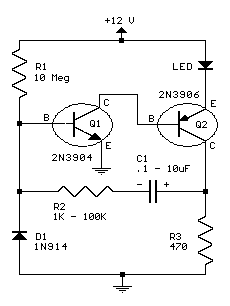
 This circuit will flash a bright red LED (5000 mcd) as an attention getting device or fake car alarm. Component values are not critical and other transistors may be used. Flash duration is determined by R2 and C1 and is approximately 3 time constants (3*R2*C1). Brightness is controlled by R3 wich limits the LED current to about 20 mA for values listed. R1 provides bias for the transistors which should be low enough not to saturate Q2 with the capacitor disconnected. If the circuit does not oscillate, R1 may be too low or R2 may be too high. D1 allows for higher duty cycle operation and limits the reverse voltage at the base of Q1 to -0.7 V. D1 may be omitted for low voltage (3-9) and low duty cycle operation. Most parts available at Radio Shack.
Original scheme edited by Bill Bowden, http://www.bowdenshobbycircuits.info
No comments:
Post a Comment